The small current is a high resistance. There are two basic techniques for measuring small currents: the shunt method and the feedback amperometric method. In the test, in the ideal case, the ammeter has no effect on the circuit at all. However, in actual measurements, multiple sources of error may occur. As we discuss below, these sources of error can cause significant measurement uncertainty.
Definition of small current
Because the IC tester is high-end measurement, it will be affected by internal switches, leads, pcb boards, etc., so the minimum current range is generally about 1UA; some discrete device testers such as JUNO machines use low-end measurement, plus special wiring, etc. The way can reach the NA level. What we are discussing here is to test the current below NA or NA in a simple and versatile way.
IV conversion circuit principle
  
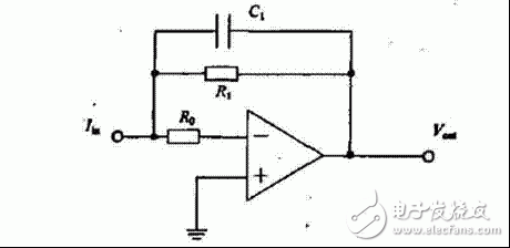
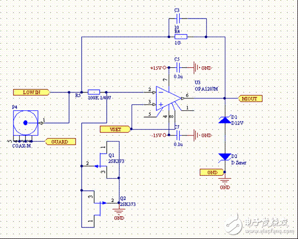
Circuit Analysis 1: Clean Power Supply
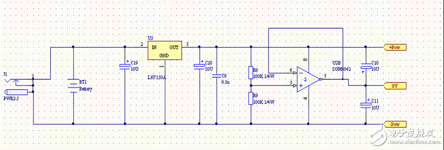
Circuit Analysis 2: Op amp selection
Requirements: The most important parameter for testing small currents is Ib. To do a microcurrent test, Ib must choose a small one. Actually. Ib always exists, and it can also compensate, zero, and cancel. Of course, it is not as good as Ib, because Ib itself is very unstable, which will bring current noise, especially its large temperature coefficient, which will largely interfere with the test results. On the other hand, the offset voltage Vos between the positive and negative inputs of the op amp will also affect the exact test. Vos is directly superimposed on the output signal. Assuming Vos=10mV, then it is originally 1V output, there is 1.01V after superposition, which forms a 1% error. Assuming that the input current is small, 0.1pA, then the calculated output is only 0.1V, and the actual output is 0.11V, the effect is even larger, reaching 10%. Therefore, Vos is still small. If Vos is not small enough, it can be largely offset by the compensation circuit. However, Vos has a temperature coefficient, and the final output of the temperature change is also changed, which makes the temperature coefficient of Vos one of the important indicators.
Circuit Analysis 3: R4 Feedback Resistor
RF is determined by three factors:
1, what kind of sensitivity and noise to achieve;
2, easy to buy?
3. What is the IB of the op amp used? IBXRF is a major factor affecting resolution.
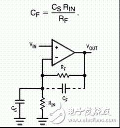
Circuit Analysis 4: Choice of Cf
It is also three factors:
1, cancel the input capacitance;
2, affect the time constant, f = 2Ï€RC
3, increase the capacity of the op amp drive capacitor load;
Circuit Analysis 4: Capacitor Selection
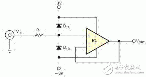
Circuit Analysis 5: Input Protection
1. The input of the op amp is a resistor.
2. Add two back-to-back diodes.
Requirements: Very low leakage current, proper positive current

Input protection (increasing leakage)
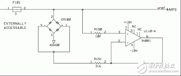
Circuit Analysis 5: Input Protection (34401A Practice)
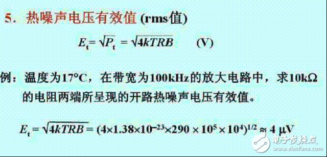
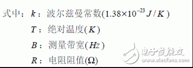
Resistance noise
The theoretical maximum limitation of small signal measurements is the output internal resistance of the signal source.
Ups Power Transformer,Computer Network System,Power Electronic Equipment,Power Transformer
SANON DOTRANSÂ Co., Ltd. , https://www.sntctransformer.com