The product automatic counter based on single-chip microcomputer has the advantages of intuitive and accurate counting, and has been widely used in various industries. There are many forms of digital counters. In general, there are two types of contact and non-contact. In the development of technology, non-contact infrared counters have been widely used. The design adopts a pair of infrared transmitting and receiving tubes as the signal detecting head of the infrared counter, and has the characteristics of low price, good anti-interference, simple structure and convenient operation. The guiding idea is to use infrared light-emitting tubes to emit infrared rays, and the infrared receiving tube receives the infrared rays, and amplifies and rectifies them to form a low-level signal. When someone or something blocks the infrared light, the receiving tube does not receive the infrared signal, the amplifier will output a high level, and this level signal is sent to the MCU for control counting, and the digital tube displays the value. This gives the number of people or things to be counted.
1 Introduction1.1 Preface
In today's fast-moving society, manufacturers basically use assembly line technology for product production operations, and how to perform real-time, effective and accurate automatic counting of their online products has become a concern of the majority of manufacturers. The traditional mechanical or electronic counter (mainly composed of digital circuit integrated components) is more complicated, the number of components is large, the failure rate is high, the maintenance is difficult, and the setting of the predetermined value is not convenient, the function is not easy to change and the function Too single, the scope of application is narrow. The counter based on single-chip microcomputer has the advantages of real-time, accurate, reliable, stable counting, etc. It has become the first automatic counting device of the majority of manufacturers.
1.2 topic selection background
Computer technology has developed rapidly. Counting devices and products developed based on single-chip technology have been widely used in various fields. SCM technology products and equipment have promoted the improvement of production technology. Enterprises urgently need to master a large number of MCU technology and can develop, apply and maintain these. The advanced engineering and technical personnel of intelligent products, with the characteristics of small size, strong function, high reliability, high performance and price ratio, have become an important means to realize industrial production technology advancement and develop electromechanical integration and intelligent measurement and control products. Or partial implementation, but to achieve these goals perfectly, there is still a lot of work to be done for the designer, rather than seemingly overwhelming. The electronic counter is a versatile electronic measuring instrument that utilizes The electronic method measures the number of pulses input over a certain period of time and displays the results in digital form.
1.3 Design requirements
(1) The whole system has strong anti-interference ability (2) Counting range: 00~99 (3) Accurately display the count value (4) With automatic clearing ability
1.4 Market Development Overview
Today's product automatic counters are mostly non-contact, and various types of dedicated test chips have been developed. The use of the AT89C51 as a control unit, supplemented by a variety of peripheral hardware, has become a trend in the field of automatic counting applications. How to improve the real-time performance, anti-interference ability and stability of the automatic counter is the main subject of automatic counting production research at home and abroad. The automatic counting of products is mainly used in the assembly line of the factory, often in extremely harsh environments such as high temperature and high noise. The AT89C series of single-chip electronic product counters often operate in this environment when misoperation (single-chip program runs away) or crashes (programs enter an infinite loop), which is also fatal based on the automatic counters of the product.
1.5 The main content of this design study should solve the problem
The main contents of the automatic counting research based on single-chip microcomputer include: If the detection circuit and AT89C51 single-chip microcomputer are used to count the external counting pulse, the counting display control, the selection of the LED display driving module, and the expansion of the AT89C51 single-chip microcomputer. The main problem to be solved in this design is how to improve the anti-interference ability and stability of the AT89C51 microcontroller.
2. Design of automatic counter based on single chip microcomputer2.1 Scheme Argumentation and Choice
Scheme 1, Figure 2-1
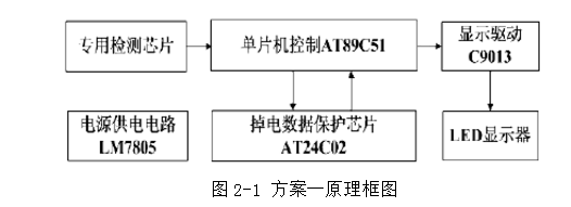
The principle of the first solution is as follows: the professional detection chip is sent to the control unit AT89C51 after it is counted, and the on-chip counting and display programming is performed. 74LS245 is an LED driver chip that can drive four 7-segment digital tubes at the same time. AT24C02 is an EEPROM module, which can save the intermediate useful result of the single-chip microcomputer operation. It is suddenly power-off, when the power is turned off or the instantaneous power supply voltage is unstable, It will cause data loss or data mis-writing, and it can also read out the saved data content after power-on, which greatly enhances the anti-interference ability.
Option 2, as shown in Figure 2-2
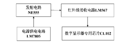
The principle of scheme 2 is as follows: the infrared transmitting circuit (with NE555 as the core) and the infrared receiving circuit (by LM567 as the core) constitute the infrared detecting unit and form the counting pulse. The counting display part uses the four-in-one chip CL102, which is set decoding and driving. , latch, display as one.
Scheme 3, as shown in Figure 2-3
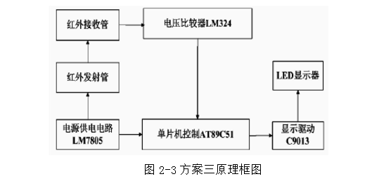
The principle of scheme 3 is as follows: the characteristics of the infrared receiving tube are adopted (that is, the infrared receiving head can take the reference voltage in the principle of dividing the infrared light resistance, and then the high voltage and low voltage can be output through the voltage comparator, and when the infrared light is irradiated, the infrared receiving The voltage of the series connected resistor is very large, which can make the voltage comparator LM324 output low level; when there is no infrared light, the voltage of the infrared receiving head series resistor is small, which can make the voltage comparator LM324 output It is high level and then processed by the MCU to output accurate count values.
Each of the above three options has its own advantages:Solution 1 can perfectly realize the automatic counting function of the product and can make the system in an abnormal state and anti-interference through the peripheral dedicated chip to a very good solution, the peripheral circuit is relatively simple to set up, and belongs to the high-end automatic counting product in the market. At the same time it also exposed a major problem; such products have not gained popularity due to the cost of being too expensive. If you use this scheme for design, you only need to know the pin function of each dedicated chip and the peripheral connection method to realize automatic counting. It is not very good for my purpose of graduation design, so although the most perfect solution for this solution is also Only give up.
Option 2 is a simple product automatic counter, which is low in price and accurate in counting. However, when the system is in an abnormal state, the work is very unstable. It is also a phase-out product in the current automatic product counting market, and is only used for low counting requirements. In the occasion, this solution is too simple to be used.
The third option is the plan for graduation design. The reason why the program is mainly used is that it has a wide range of knowledge and can achieve accurate and stable automatic counting, but it also has a disadvantage. The anti-interference ability of the whole system is relatively poor. The system cannot save data after power failure, and it is prone to misoperation or crash when the system is in an abnormal state. This is also a difficult problem in this design.
2.2 System overall block diagram and principle
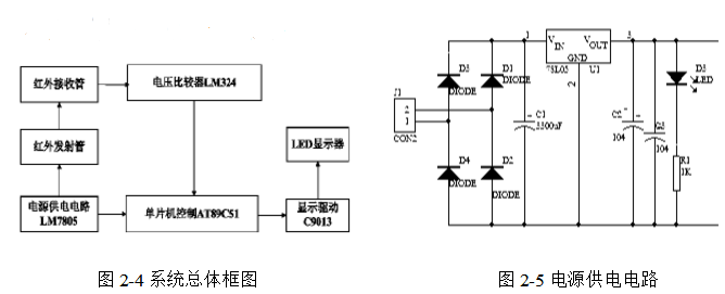
Principle: The guiding principle of the circuit is that the infrared emission tube emits infrared rays, and the infrared receiving tube receives infrared rays, and when the receiving tube has infrared rays, the resistance is relatively small, and when the wireless external line is irradiated, the resistance is relatively large, so that a voltage comparison can be performed. Comparing with a reference voltage, when there is light, the resistance of the infrared receiving tube is relatively small, then the voltage dividing voltage in series with it will increase, so the voltage comparator will output a high level; when no light is irradiated When the infrared receiving tube has a relatively large resistance, the voltage comparator outputs a low level. This is the external count level signal. This level signal is sent to the AT89C51 MCU for counting control. After the expansion and display drive, the final display process is completed. 2.3 system unit circuit design
2.3.1 Power supply circuit
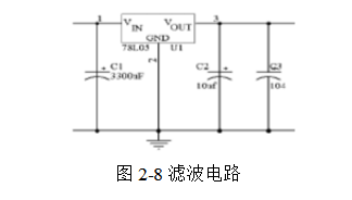
As shown in Figure 2-5, the power supply part adopts transformer step-down, bridge rectification, capacitor filtering, and three-terminal regulator 7805. After power supply is regulated as shown in Figure 2-6, the power supply with 220V is reduced to 6V by transformer. AC power, and then through four rectifier diodes (D1 ~ D4) as shown in Figure 2-7 bridge rectifier into DC voltage, after C1 filtering, input 7805 chip voltage regulator into 5V DC power supply for infrared transmission, receiving circuit, AT89C51 and other power supply .
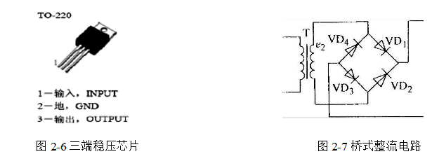
Bridge rectifiers are the most common circuits that use diodes for single-conduction to rectify, and are commonly used to convert AC to DC. working principle:
Bridge rectification is an improvement over diode half-wave rectification.
Half-wave rectification utilizes the diode's unidirectional conduction characteristic. In the case of inputting a standard sine wave, the positive half of the sine wave is obtained and the negative half is lost.
The bridge rectifier uses four diodes, which are connected in pairs. The positive half of the input sine wave is the two tubes conducting, and the positive output is obtained. When the negative half of the sine wave is input, the other two tubes are turned on, because the two tubes are Reversed, so the output still gets the positive half of the sine wave. The bridge rectifier is twice as efficient as the input sine wave than the half-wave rectification.
Bridge rectification is the first step in the conversion of AC to DC. Bridge rectification is also called rectifier bridge stack.
The bridge rectifier is a multi-rectifier diode for bridge connection, and the outer casing is made of insulating plastic. The high-power rectifier is wrapped with a metal shell outside the insulation layer to enhance heat dissipation. The bridge rectifier has many varieties, excellent performance, high efficiency and good stability. The maximum rectification current is from 0.5A to 50A, and the highest reflection peak voltage is from 50V to 1000V.
The rectifying circuit is a circuit that converts alternating current into direct current, but the pulsating component of the direct current output is large, and the pulsation coefficient of the direct current power supply required by the electronic device (the ratio of the amplitude of the voltage or current to the average value is called The pulsation coefficient S) is required to be less than 0.01, so the voltage of the rectified output must take certain measures.
Try to reduce the ripple component in the output voltage. At the same time, try to save the DC component in the output voltage so that the output voltage is close to the ideal DC power. Such a circuit is a filter circuit in the DC power supply.
Commonly used filter circuits are passive filtering and active filtering. The main forms of passive filtering are capacitive filtering, inductive filtering and complex filtering (including inverted L-type, LC filtering, LCrr-type filtering, also known as electronic filters).
The magnitude of the pulsating component in the direct current is represented by a pulsation coefficient. The larger the value, the worse the filtering effect of the filter.
The pulsation coefficient (S) = the maximum value of the AC component of the output voltage / the DC component of the output voltage is larger when the angular frequency of the alternating current is constant. The larger the C1 is, the smaller the pulsation coefficient is, that is, the better the filtering effect. When the value of R increases, the DC voltage drop across the resistor increases, which increases the internal loss of the DC power supply. If the capacitance of C2 is increased, the volume and weight of the capacitor will be realized. .
In order to solve this problem, we have a filter absorption circuit before and after the voltage regulation, using the charge and discharge of the capacitor to compensate the voltage fluctuation of the AC component as shown in Figure 2-8.
2.3.2 Infrared detection section
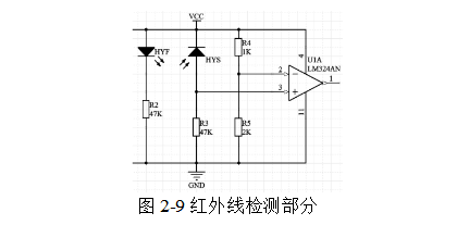
As shown in Figure 2-9, the infrared detection part is completed by a pair of infrared transmitting and receiving tubes. When the circuit works normally, the obstacles are blocked, and the infrared receiving head is irradiated with infrared rays. At this time, the resistance of the infrared receiving head is small and large. Part of the voltage is applied to R3, which is the forward input voltage of the voltage comparator LM324, and the negative input voltage is divided by R4 and R5.
To, and the voltage divided by R3 is greater than the reference voltage value, so the voltage comparator LM324 outputs a high level; when there is an opaque obstacle between the infrared transmitting and receiving tubes, the infrared receiving head has no infrared radiation. At this time, the resistance of the infrared receiving head is very large, most of the voltage is applied to the infrared receiving head, which is also the positive input voltage of the voltage comparator LM324, and the negative input voltage is also obtained by dividing the R4 and R5, and the original The voltage is the same. At this time, the voltage divided by R3 is smaller than the reference voltage value, so the voltage comparator LM324 outputs a low level.
2.3.3 Digital tube display part
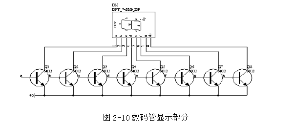
Figure 2-10 Digital tube display part
The display part is shown in Figure 2-10 through the 9013PNP transistor to complete the bit selection operation. Then through the software decoding to complete, in order to take into account the digital tube in the dynamic scanning, each time a digital tube is lit for a short time, this will affect the brightness of the digital tube, so here with the 9013 triode as a digital tube A segment selection driver level.
In the design, the segment code output port uses the P0 port as the output port, and the P0 port is the open drain circuit. Although there is a strong current sinking capability, the current drawing capability is very poor, so a 10th row resistance is added to the P0 port as Connect the resistor. The function of the pull-up resistor is that when the input on the P0 port of the single chip is 0, the current on the pull-up resistor flows directly into the single-chip microcomputer, so that the segment code of the digital tube is kept low, so the digital tube does not emit light at this time; When the output of the P0 port of the MCU is 0, then the pull-up resistor can make the current sink into the MCU, so the current on the resistor is flowing into the digital tube, so the digital tube is illuminated at this time. Digital Tube).
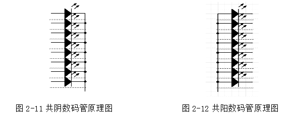
The digital tube is actually eight LEDs, which are connected in two ways. If the cathodes are connected together, the digital tube formed in this way becomes a common cathode digital tube as shown in Fig. 2-11; if the anodes are connected together The digital tube formed by this method is a common digital tube as shown in Figure 2-12.
(1) Features of LED digital tube
It can drive light under low voltage and low current, and can be compatible with CMOS and TTL circuits. It has very short response time ("0.1s"), high frequency characteristics, good monochromaticity and high brightness. Small size and light weight. Good impact resistance;
Long life, use more than 100,000 hours, even up to 1 million hours, and low cost. The display part adopts the software decoding mode. The so-called software decoding is to organize the segment selection codes of each character into a table. It is necessary to display a character to first check the table to obtain the segment selection code, and then send it to the segment code line of the display.
The dynamic display of software decoding is often used in the application system of single chip microcomputer. (2) Digital tube dynamic scanning
Since all the segments of the LED digital tube are controlled by an 8-bit I/O port, at each instant, my LED will display the same character. In order to display different characters for each bit, scanning must be performed. The method illuminates the LEDs in turn, that is, only one character is displayed at each instant. At this moment, the segment selection control I/O outputs the corresponding character segment selection code (font code), and the bit selection controls the I/O port to send the strobe level at the display bit (because the LED is common yin, it is sent Low level, when the LED is common yang, it is sent to the high level) to ensure that the corresponding character is displayed in the bit, so that each bit displays the character that should be displayed. The delay of the segment selection code and the bit selection code is 1ms after each input, because the visual persistence time of the human eye is 0.1s: (100ms), so the interval of each display does not have to exceed 20ms, and the delay is kept for a period of time. Causes the visual persistence effect, giving the appearance that each digital tube is always bright.
2.3.4 MCU count and control part
(1) Counting part
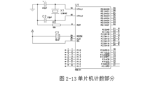
The counting part is shown in Figure 2-13. It is controlled by the single chip AT89C51. The basic principle is that when an infrared detecting part detects that an object has passed, the series resistance of the infrared receiving circuit decreases the partial pressure, so that the positive input terminal of the voltage comparator is smaller than the voltage of the negative input terminal, so that the voltage comparator outputs one. Low level signal, this signal will be supplied to the microcontroller for counting control.
There are three options for the counting part: external interrupt, T0 or T1 counter pulse statistics, and query method. The main function of the T0 or T1 counter is to count the number of pulses in a certain period of time. We are not here.
The research object is to display the current count value on the display in real time through the number of items in a certain period of time, so we cannot use the T0 or T1 counter here;
The query method is that the CPU generates a count pulse at a certain time or at any time. We know that the time that the CPU spends about one pulse per query is one machine cycle, that is, 12 oscillation cycles, that is, 1 ïs. The transmission speed of the external pipeline is too slow compared to the operating speed of the microcontroller. If you insist on using the query method to calculate the transmission speed of the statistical object, this is too wasteful for the time resource of the single-chip microcomputer. In the design of the single-chip microcomputer product, the time resource and space data are especially precious and cannot be easily wasted, so the query scheme is discarded.
The external interrupt method uses the second function of the P3.2 port, INT0 interrupt. At this time, when a low level is generated, the microcontroller will automatically enter the interrupt service routine to handle the external interrupt problem, but at this time, due to external interference Or the characteristics of the object may be interrupted repeatedly, which may cause miscalculations, recalculations, etc. The problem we deal with here is that we no longer use level triggering, but use negative edge triggering, so only A complete pulse is generated before a negative edge is generated, which solves the error problem in a large program.
In summary, in this design, the most reasonable is to use the external interrupt mode to count.
(2) MCU control part
There are two schemes for controlling the digital tube of the single-chip microcomputer. One is the query method, and the other is the interrupt method. The interrupt here is no longer an external interrupt, but the timer is used to generate the timer interrupt, thus controlling the display of the digital tube. .
The query method is similar to the pulse query method mentioned above. The main program constantly queries and displays the lighting of the digital tube, and a delay program is inserted between each digital tube, and these delay programs are generally It is a method of using a null operation to delay, which wastes a lot of time and space data. This scheme is generally not used in engineering design and product production.
The interrupt method uses the overflow generated inside the microcontroller to count and time, so that it can accurately perform the corresponding work at a certain time or at a specified time. In this design, the digital tube is scanned every 1ms to illuminate the digital tube.
However, in the corresponding program segment of the above display and counting, you may encounter both of them entering the interrupt problem at the same time. If such a problem is encountered, it may cause the microcontroller to crash or the program runs away. In order to avoid such a situation In production, we must set priorities here. In industrial production, it is most important to calculate the correct value. Therefore, we must set the external pulse as the priority.
The AT89C51 has the following standard features:4K bytes of FLASH flash memory, 128 bytes of internal RAM, 32 I/O lines, two 16-bit timer/counters, one 5-vector two-stage interrupt, one full-duplex serial communication port, on-chip oscillator circuit, At the same time, the AT89C51 can be reduced to 0HZ for static logic operation and supports two software power-saving modes. The idle mode stops the CPU, but allows the RAM, timer/counter, serial communication port, and interrupt system to continue to operate. The contents of the ROM are saved after power down, but the oscillator stops working and all other components are disabled until the next hardware reset.
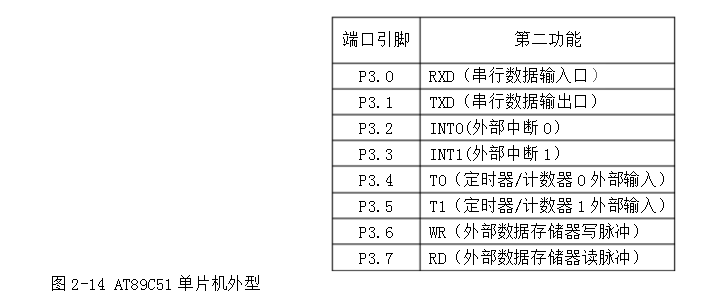
The AT89C51 has a total of forty pins as shown in Figure 2-14. It is closed by dual in-line type. The functions of each pin are as follows:
P0 to P3: Data input and output ports.
Port P0: An open-drain 8-bit quasi-bidirectional I/O port that acts as an open-drain output port that can drive eight LS-type TTL loads per bit. When the P0 port is used as an input port, first set all the latches to the port latch (address 80H). At this time, all the pins of the P0 port are floating, which can be used as a high impedance input. Write me when working as an input port. This is the meaning of quasi-bidirectional.
Port P1: An 8-bit bidirectional I/O port with an internal pull-up resistor. The output buffer of P1 can drive (sink or output current mode) four TTL inputs. When a port is written to 1, the internal pull-up resistor can be pulled to the high potential, which can be used as an input port. When P1 is used as an input port, because of the internal pull-up resistor, those pins that are pulled low by an external signal will output a current (ILI).
Port P2: An 8-bit bidirectional I/O port with internal pull-up resistors. The output buffer of P2 can drive (absorb or output current mode) 4 TTL inputs. When a port is written to 1, the port is pulled high by the internal resistor, which can be used as an input port. When P2 is used as an input port, because of the internal pull-up resistor, those pins that are pulled low by the part signal output a current (ILI).
Port 3: An 8-bit bidirectional I/O port with internal pull-up resistors. The output buffer of P3 can drive (absorb or output current mode) 4 TTL inputs. When writing 1 to the product, the product is pulled to a high potential by an internal pull-up resistor, which can be used as an input port. When P3 is used as an input port, because of the internal pull-up resistor, those pins that are pulled low by an external signal will output a current: (ILI).
In the AT89C51, the P3 port is also used for some multiplexed functions, that is, the second function, and its multiplexing function is shown in Table 2-1.
In addition, the RST pin is the input of the reset signal, the reset signal is active high, and its effective time should last for 24 oscillation cycles (ie, two machine cycles). If the frequency is 6MHZ crystal, the reset signal duration is It should be more than 4 ïs to complete the reset operation.
3, reset circuit
The entire reset circuit includes two parts inside and outside the chip. The reset signal generated by the external circuit (Figure 2-15) is sent to the Schmitt trigger, and then the on-chip reset circuit samples the output of the Schmitt trigger at S5P2 of each machine cycle, and then gets an internal reset. The signal required for operation.
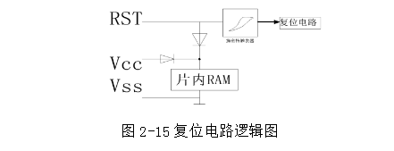
The reset circuit is further divided into a manual reset and a power-on reset.
Power-on reset: The capacitor is realized by charging at the moment of power-on, and its circuit is shown in Figure 2-16. At the moment of power-on, capacitor C is charged through resistor R, and a positive pulse appears at the RST terminal for reset.

Manual reset: The so-called manual reset is to make the MCU enter the reset state through a push button switch. After the system is powered on, it needs to be reset, and it can be realized by manually gaining the bit. Generally, it combines the RC reset and the manual reset. As shown in Figure 2-17
2.4 system flow chart design
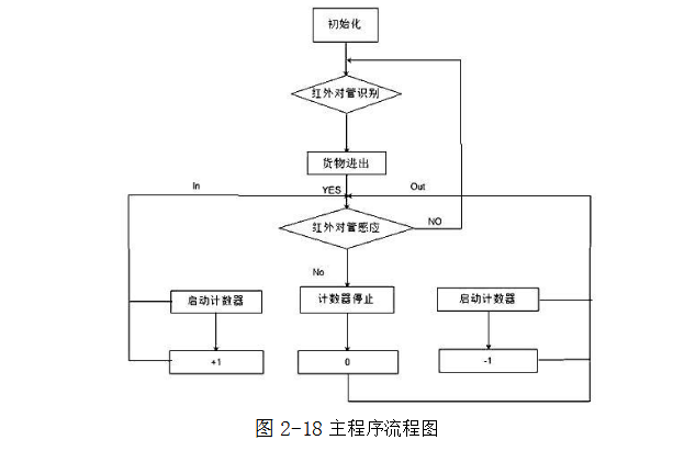
2.5 overall circuit diagram
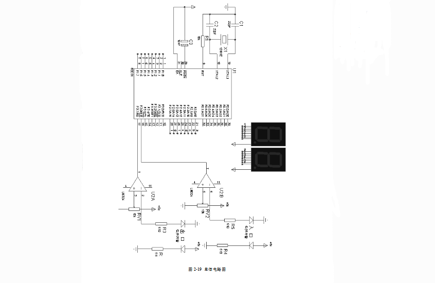
1. Preparation before welding
First of all, you should be familiar with the assembly drawing of the printed circuit board, and according to the drawings, check whether the component model, specification and quantity meet the drawing requirements, and prepare the lead forming of the components before assembly, because the production is portable. Shake the stick, so here I chose the mobile power supply for the power supply.
2. Welding sequence
The order of component soldering is: resistors, capacitors, diodes, integrated circuits, high-power tubes, and other components are small and large.
3. Welding requirements for components (1) resistor welding
According to the figure, the resistor is accurately loaded into the specified position. The mark is required to be up and the child direction is consistent. After installing the same specification, install another specification and try to make the resistance level consistent. After soldering, the excess pins on the surface of the printed circuit board will be cut off.
(2) Capacitor welding
Put the capacitor in the specified position according to the figure, and pay attention to the polarity of the capacitor. The "+" and "one" poles cannot be connected incorrectly. The marking direction on the capacitor should be easy to see. First install glass glaze capacitors, organic dielectric capacitors, ceramic capacitors, and finally electrolytic capacitors.
(3) Soldering of the diode
Diode soldering should pay attention to the following points: First, pay attention to the polarity of the anode cathode, can not be wrong; second, the model mark should be easy to see visible; third, when soldering the vertical diode, the welding time of the shortest lead can not exceed 2S.
(4) Integrated circuit welding
First, check the model and pin position according to the requirements of the drawings. When soldering, first solder the two pins of the edge to position it, and then solder from top to bottom from left to right.
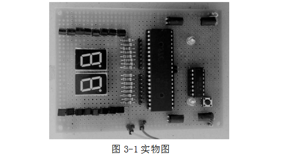
Cm Nozzle,Panasonic Cm Nozzle,Smt Cm Nozzle,Panasonic Smt Cm Nozzle
Shenzhen Keith Electronic Equipment Co., Ltd. , https://www.aismtks.com