Nowadays, more and more people want to read the wiring diagram of the electric vehicle controller, not only because of the popularity of electric vehicles, but also because more and more people are eager to do it themselves and can solve all the problems of their own cars. People have come from a simple layer of understanding.
More and more consumers will choose to troubleshoot their own problems when there are problems with electric vehicle accessories. They need to replace the zeros. I will also attach the wiring diagrams here to facilitate everyone's understanding. Speaking of the wiring method of the electric car alarm, it is very simple in principle. However, it is necessary to look for the positive and negative poles of the converter. How to connect the 60v lead-acid battery of the textile electric vehicle with the 60v battery in parallel, and connect the lead-acid battery and the positive electrode of the lithium battery to the 50A power diode in parallel.

The general battery car electric buck is called DC/DC, commonly known as power converter, the power generally has a certain margin, but if your audio power is too large, it is recommended that you add another voltage converter, so that the car can not be opened.
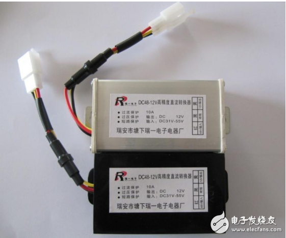
The electric vehicle converter has three lines, which are red, yellow, black and red, which are connected to the lock line (input), yellow is the positive 12V (output), black is the negative (equivalent to the ground wire)
There are two things to note:
1. The positive and negative poles of the power supply cannot be mistaken, otherwise the speaker or converter may be burned out;
2, pay attention to the converter output current size, such as the converter's maximum output current is 1 amp, the active speaker's full load power can not exceed 10 watts, otherwise the converter may burn.
Electric vehicle with 12V converter wiringThis is very simple, it is very simple to first understand the principle of the converter and the boundary requirements - the general converter can convert 48~64V voltage to 12V and then output (relative to the negative voltage difference) then the converter There will be 3 lines, red, black, and yellow. The specific connection line is - red line high voltage input (36~64V), black line (negative), and yellow line is 12V output. You can install the converter in the front of the car, where the line is better to choose - you can connect the red wire to the electric door lock output, the black wire to the common negative pole, (the negative pole on the lamp or speaker can be used, very good Look for it, the remaining yellow wire is connected to the switch of the light you want to install.

If the electric vehicle is to be replaced, it is often seen that the electric vehicle controller has a colorful exposed wiring and is overwhelmed. So how can the electric vehicle controller quickly identify and connect to the electric vehicle? The method: Today we will take a closer look at the meaning of the various lines of the electric vehicle controller.
First determine the positive and negative poles of the power supply, and the electric door lock line: the method is to first put the multimeter on the DC file, then connect the negative pole of the multimeter [black line] to the negative pole of the battery [ground] and then use the positive pole of the multimeter [red line] One quantity, the voltage is the positive pole [slightly higher than the power supply voltage], and the voltage is the negative pole. Here, the power supply is three wires, and the one is the electric door lock line. The characteristic of this line is that Turning on the key is the same as the power supply voltage, turning off the key and no voltage.
Next, close the three lines of the key connection power cord and the electric door lock line: the controller power cord is thick red for the positive pole and thick black for the negative pole. After connecting, turn on the key, and then measure the voltage of the power supply voltage and the electric door lock line is normal. Then, the power supply voltage of the line is about 5V [red and black line], and the power supply voltage of the Hall line is about 5V. Black line] [Don't forget the multimeter hit the DC file].
The third voltage is normally connected to the white learning line: if the reverse is unplugged once, the motor is rotated and the learning line is pulled out. It is possible to connect the wire, generally by color. If it is not possible, the switch will be broken. Then unplug the switch and connect the controller to the red and green lines of the line. The motor rotates normally, and it proves that there is a question in the turn and change the handle.
After the fourth motor rotates normally, the brakes break the wires, the Hall line, the instrument line, and so on.
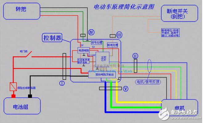
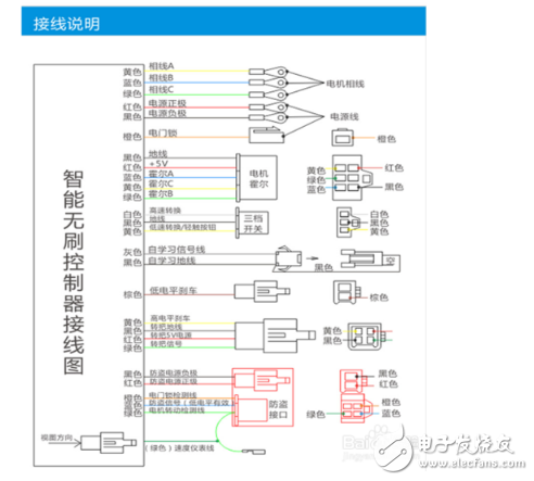
What is the meaning of each line of the fifth controller? (The picture below shows the circuit diagram of the high-standard electric vehicle controller)

What is the meaning of the various lines on the sixth tram: find the 5 Hall lines of the motor's 3 phase lines along the motor, remove the turn to find 3 turn lines, and remove the brakes to find 2 brake lines. Disassemble the battery and you can see the "+" power supply positive "-" power supply negative. In general, it is easy to understand and most accurate when it is found in large parts and installed in large parts.
Seventh if the motor is not normal, it is possible that the Hall is broken. The method of testing Hall is good or bad: the vehicle is charged and tested. First connect the lines and connectors, and pull the multimeter to the DC voltage 20V. First confirm that the controller has 5V power output, then use the black test pen to connect to the ground wire of Hall. The red test pen is connected to three signal lines respectively. At the same time, the motor is gently turned by hand. When the Hall is normal, the multimeter will be 0V-- The data of the 5V pulse voltage shows that if there is no pulse voltage when measuring a certain Hall, the Hall will be broken. [This case can also be detected by a pointer multimeter, and the pointer swings between 0V and -5V. Hall is good; if the pointer does not swing, Hall is bad] This method is the most reliable method, provided that it is powered.
The eighth instrument line: Disassemble the meter and find that the instrument has 2 wires, one connected to the anti-theft interface and one on the instrument line of the controller.
The ninth to find the turn line: remove the turn will find the turn on the three lines, you can find the color, or use a multimeter to measure.
The tenth brake disconnected wire: When the brake lever is removed, it will be found that the brake has 2 wires [the brake is a normally open switch], and the two wires can be directly connected to the controller brake power off.
After the eleventh installation is completed, use the pedal to push up the whole vehicle. Connect the controller to learn the line pair and then open the electric door lock. At this time, it will enter the self-learning. When the rotation is normal, if the motor runs in the opposite direction. Just adjust the speed control knob, you can change the running direction of the motor, and then open the learning line.
OBD Connector Section.
OBD:On Board Diagnostics.
One is to connect to the OBD interface of the vehicle through a special data line. Reading out the data and displaying it on the matching display screen is basically equivalent to adding a driving computer display screen. At ordinary times, the connecting cable can be plugged into the OBD interface all the time without removing it, and only the fixed display screen is needed. The owner can choose the data to be displayed by himself
OBD Connector Section
ShenZhen Antenk Electronics Co,Ltd , https://www.antenkcon.com