TI's DRV10983-Q1 is a 12V/24V automotive three-phase sensorless BLDC motor driver with integrated power MOSFETs for continuous drive currents up to 2A. Meets automotive specifications AEC-Q100 such as –40°C to 125°C operating temperature, HBM ESD classification level 1C, CDM ESD classification Level C4A, motor working voltage 6.2V-28V, with overcurrent protection, lock detection, anti-voltage surge (AVS) protection, UVLO protection and thermal shutdown protection. Mainly used in small pumps and fans , seat ventilation fan, HEV battery cooling fan and motorcycle fuel pump. This article describes the main features of DRV10983-Q1, functional block diagram, application circuit and evaluation module DRV10983-Q1 EVM main features, circuit diagram, bill of materials and PCB renderings.
The DRV10983-Q1 device is a 3-phase sensorlessmotor driver with integrated power MOSFETs, whichcan provide conTInuous drive current up to 2 A. Thedevice is specifically designed for cost-sensiTIve, lownoise, low-external-component-count fan and pumpapplicaTIons.
The DRV10983-Q1 device preserves register settingdown to 4.5 V and delivers current to the motor withsupply voltage as low as 6.2 V. If the power supply voltage is higher than 28 V, the device stops driving the motor and protects the DRV10983-Q1 circuitry. Is able to handle a load dump conditionup to 45 V.
The DRV10983-Q1 device uses a proprietary sensorless control scheme to provide continuous sinusoidal drive, which significantly reduces the pure tone acoustics that typically occur as a result of commutation. The interface to the device is designed to be simple and flexible. Directly through PWM, analog, orI2C inputs. Motor speed feedback is available through both the FG pin and the I2C interface simultaneous.
The DRV10983-Q1 device features an integrated buck regulator to step down the supply voltage efficiently to 5 Vfor powering both internal and external circuits. The 3.3-V LDO may also be used to provide power for external circuits. The device is available in either a sleep The standby mode (8.5 mA) version (DRV10983SQ) leaves the regulator running and the sleep mode (48 μA) version (DRV10983Q) shuts the regulator off. Use the standby mode or a standby mode version to conserve power when the motor is not running. Mode version in applications where the regulator is used to power an external microcontroller. Throughout this data sheet, the DRV10983-Q1part number is used for both devices ie DRV10983Q (sleep version) and DRV10983SQ (standby version), except for specific discussion of sleep vs standby Functionality.
An I2C interface allows the user to reprogram specific motor parameters in registers and to program the EEPROM to help optimize the performance for a given application. The DRV10983-Q1 device is available in a thermallyly-efficient HTSSOP, 24-pin package with an exposed thermal pad. The operating ambient temperature isspecified from –40°C to 125°C.
Main features of DRV10983-Q1:
• Qualified for Automotive Applications
• AEC-Q100 Qualified With the Following Results:
– Device Temperature Grade 1: –40°C to 125°CAmbient Operating Temperature Range
– Device HBM ESD Classification Level 1C
– Device CDM ESD Classification Level C4A
• Operation Voltage Range:
– Motor Operation, 6.2 V to 28 V
– Register Setting Preserved, 4.5 V to 45 V
• Supports Load Dump Voltage up to 45 V
• Total Driver H + L rDS(on)
– 250 mΩ at TA = 25°C
– 325 mΩ at TA = 125°C
• Drive Current: 2-A Continuous Winding Current (3-A Peak)
• Configurable Output PWM Slew Rate and Frequency for EMI Management
• Sensorless Proprietary Back Electromotive Force (BEMF) Control Scheme (No Need of HallSensors)
• Continuous Sinusoidal 180° Commutation
• Initial Position-Detect Algorithm to Avoid BackSpin During Start-Up
• No External Sense Resistor Required
• Flexible User Interface Options:
– I2C Interface: Access Registers for Command and Feedback
– Dedicated SPEED Pin: Accepts Either Analogor PWM Input
– Dedicated FG Pin: Provides TACH Feedback
– Spin-Up Profile Can Be Customized WithEEPROM
– Forward-Reverse Control With DIR Pin
• Integrated Buck Converter to Efficiently Provide5â€V and 3.3-V LDOs for Internal and ExternalCircuits
• Supply Current 8.5 mA With Standby Version (DRV10983SQ)
• Supply Current of 48 μA With Sleep Version (DRV10983Q)
• Protection Features
– Overcurrent Protection (Protection for Phaseto-Phase, Phase-to-GND and Phase-to-VCCShorts
– Lock Detection
– Anti-Voltage Surge (AVS) Protection
– UVLO Protection
– Thermal Shutdown Protection
• Thermally Enhanced Package
DRV10983-Q1 application:
• Small Automotive Pumps and Fans
• Seat Ventilation Fans
• Motorcycle Fuel Pumps
• HEV Battery Cooling Fans
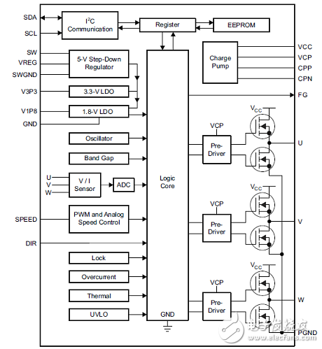
Figure 1. Block diagram of DRV10983-Q1
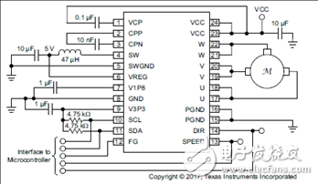
Figure 2. DRV10983-Q1 application circuit
Evaluation Module DRV10983-Q1 EVM
This user's guide provides complete details of the customer evaluation module (EVM) for the DRV10983-Q1 device including hardware implementation, jumper configuration, and operating procedure to run 3-phase BLDC motors. This EVM user's guide is intended to be used with the DRV10983 -Q1 Tuning Guideto optimally tune a user motor.
The DRV10983-Q1 EVM is a complete solution for evaluating the DRV10983-Q1, three-phase sensorlessBLDC motor drivers. Device evaluation and configuration for specific applications is possible with theprovided DRV10983-Q1 EVM GUI. This document describes the kit details and explains the functions Andlocations of test points, jumpers, and connectors present on the kit. This document is also a quick-startguide for using the GUI to tune a motor for application.
The evaluation module DRV10983-Q1 EVM includes:
• DRV10983-Q1 EVM board
• USB2ANY communication board for I2C GUI interaction
• USB cable
• 10-pin ribbon cable to connect the USB2ANY and DRV10983-Q1 EVM
• DRV10983-Q1 EVM GUI
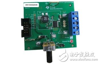
Figure 3. Evaluation module DRV10983-Q1 EVM outline drawing
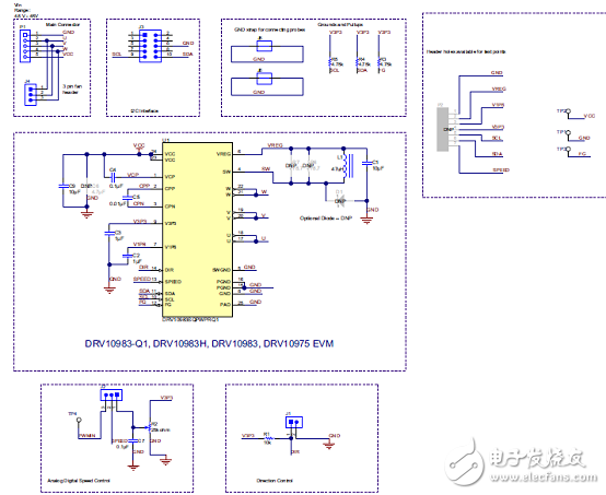
Figure 4. Evaluation module DRV10983-Q1 EVM circuit diagram
Evaluation Module DRV10983-Q1 EVM Bill of Materials:
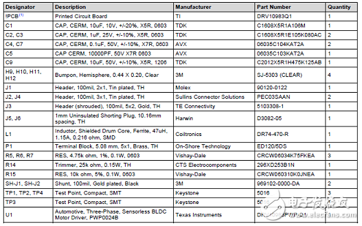
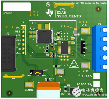
Figure 5. Evaluation Module DRV10983-Q1 EVM PCB Rendering
Magnetic Transducer External Drive Type
The magnetic transducers (External Drive Type) are versatile and customizable to different physical sizes, housings, mounting options, power consumptions. Our magnetic transducers are engineered to be used with an external drive circuit. This allows our customers the flexibility to design and customize the circuitry to meet their needs. External circuitry allows different frequency ranges to be used to create multiple sounds through excitation waveform. Our magnetic transducers come in a slim-line profile and are a cost-effective solution. Our extensive capabilities make our magnetic transducers an excellent solution for high/low tones, siren, and chime sounds.
Piezoelectric Buzzer,Passive Magnetic Buzzer,External Drive Buzzer,Magnetic Transducer External Drive Type
Jiangsu Huawha Electronices Co.,Ltd , https://www.hnbuzzer.com