T-type resistor network D/A converter:
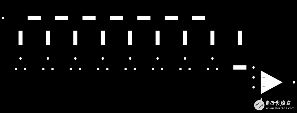
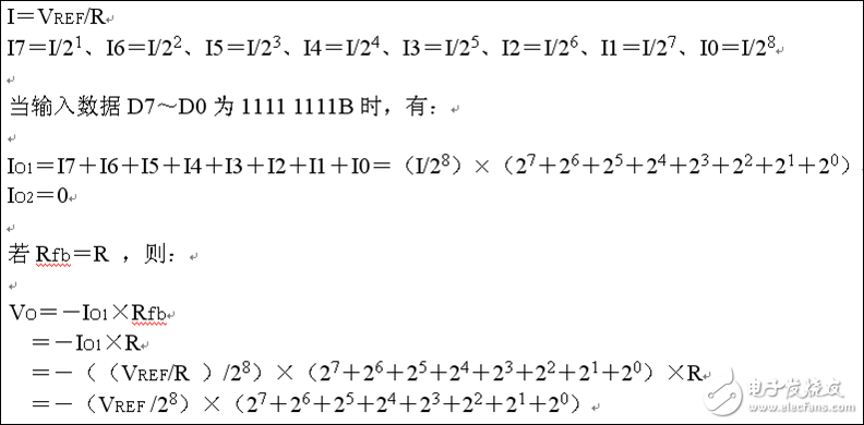
1, resolution
Resolution is the amount of change in the corresponding output analog (voltage or current) when the least significant bit (LSB) of the input digital value changes. It reflects the minimum change in the output analog.
The resolution has a definite relationship with the number of digits of the input digits and can be expressed as FS / 2^n . FS represents the full-scale input value and n is the binary digit. For a full-scale of 5V, the resolution is 5V/256=19.5mV when using an 8-bit DAC, and 5V/4096=1.22mV when using a 12-bit DAC. Obviously, the higher the number of bits, the higher the resolution.
2, linearity
Linearity (also known as nonlinearity error) is the maximum deviation between the actual conversion characteristic and the ideal linear characteristic. Often expressed as a percentage relative to full scale. For example, ±1% means that the difference between the actual output value and the theoretical value is within ±1% of the full scale.
3, absolute accuracy and relative accuracy
Absolute accuracy (referred to as precision) refers to the maximum error between the actual output value of the analog quantity corresponding to any input digital and the theoretical value over the entire scale. Absolute accuracy is the gain error of the DAC (the difference between the actual output value and the ideal output value when the input number is all 1), the zero point error (the non-zero output value of the DAC when the digital input is all 0), the nonlinearity error and Caused by noise, etc. The absolute accuracy (ie maximum error) should be less than 1 LSB.
Relative accuracy and absolute precision have the same meaning, expressed as a percentage of the maximum error relative to the full scale.
4, set up time
The settling time is the time required for the output analog signal to reach ±1/2LSB of the full scale value when the input digital quantity changes to full scale. Is a dynamic indicator describing the D/A conversion rate.
The settling time of the current output type DAC is short. The settling time of the voltage output type DAC is mainly determined by the response time of the operational amplifier. Depending on the length of the setup time, the DAC can be divided into ultra-high speed ("1μS", high speed (10 ~ 1μS), medium speed (100 ~ 10μS), low speed (≥ 100μS) several files.
It should be noted that accuracy and resolution have a certain connection, but the concepts are different. When the number of bits of the DAC is large, the resolution is increased, and the quantization error corresponding to the influence accuracy is reduced. However, the influence of other errors (such as temperature drift, poor linearity, etc.) will still deteriorate the accuracy of the DAC.
Four: chip instance1: DAC0832
The DAC0832 is a very popular 8-bit D/A converter that interfaces directly to the microcontroller due to its on-chip input data registers. The DAC0832 is output as a current source and can be connected to an external operational amplifier when it needs to be converted to a voltage output. The chips belonging to this series also have DAC0830 and DAC0831, which can be replaced by each other. Main features of DAC0832:
Resolution 8 bits;
Current settling time 1μS;
Data input can be double buffered, single buffered or straight through;
Output current linearity can be adjusted at full scale;
The logic level input is compatible with the TTL level;
Single power supply (+5V ~ +15V);
Low power consumption, 20mW.
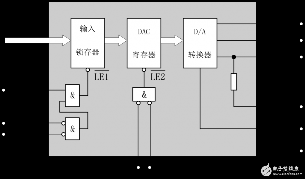
Pin descripTIon:
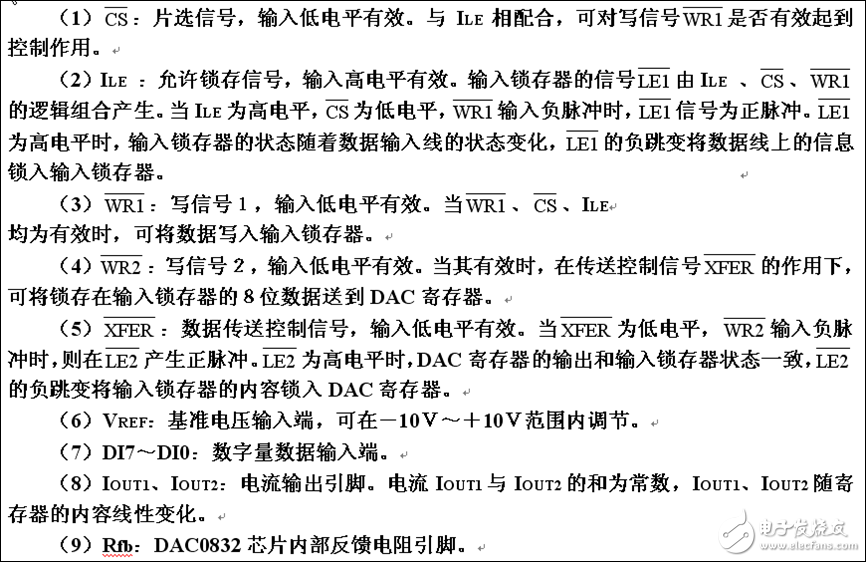
2: DAC0832 three working methods
1, single buffer working mode
This method is suitable for systems that have only one analog output, or that have several analog outputs but do not require synchronization.
Namely: default CS = XFER = 0, ILE = 1; WR is controlled separately. Buffering is controlled solely by WR.
1.1 unipolar analog output
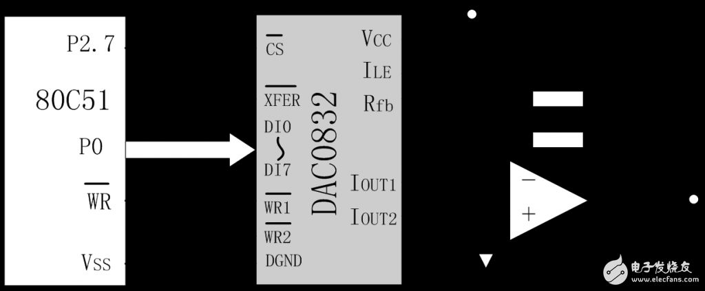
1.2: Bipolar analog output voltage
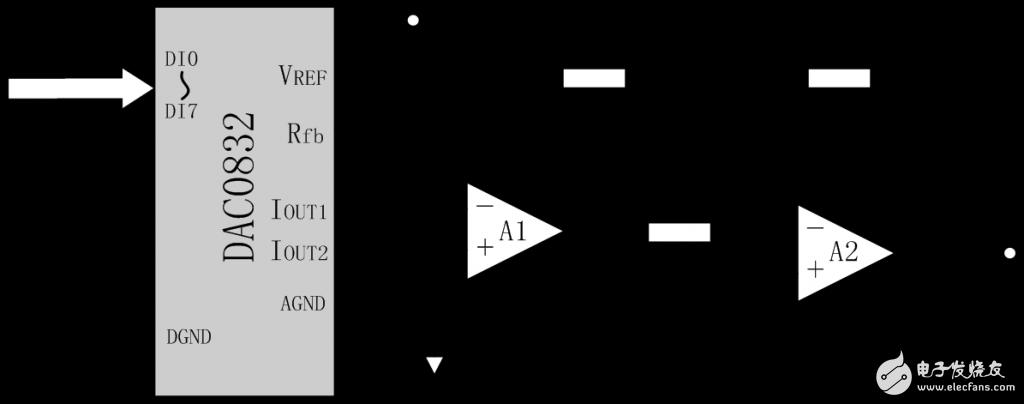
The resolution of the bipolar output is reduced by 1/2 compared to the unipolar output. This is because for the bipolar output, the highest bit is used as the sign bit, and only the 7-bit value bit.
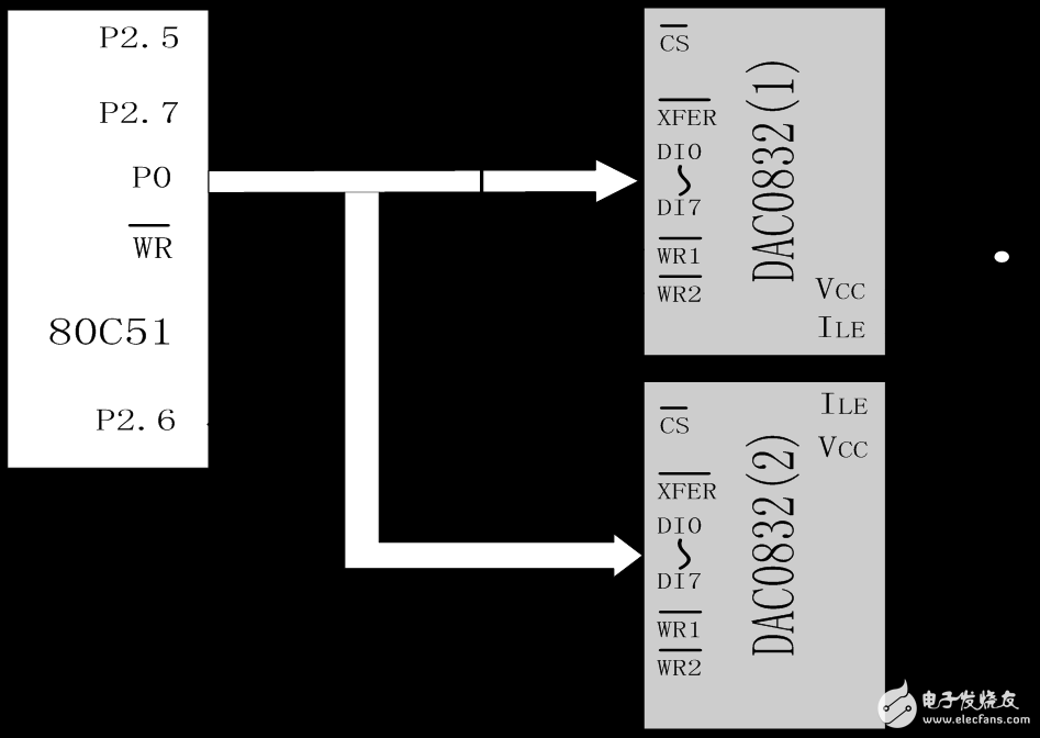
2, double buffer working mode
Multiple D/A conversion outputs. If synchronization is required, double buffer synchronization should be used.
That is: the default CS = 0 ILE = 1; WR and XFER are controlled separately, the buffer is controlled by WR and XFER.
3, straight through working methods
When the pins of the chip select signal CS, the write signal WR, and the transfer control signal XFER of the DAC0832 chip are all grounded, and the input latch signal ILE pin is connected to +5V, the DAC0832 chip is in the through mode, and once the digital quantity is input, Go directly to the DAC register for D/A conversion.
That is: CS = WR = XFER = 0, ILE = 1;
A/D converter 1. Conversion principle of successive approximation ADC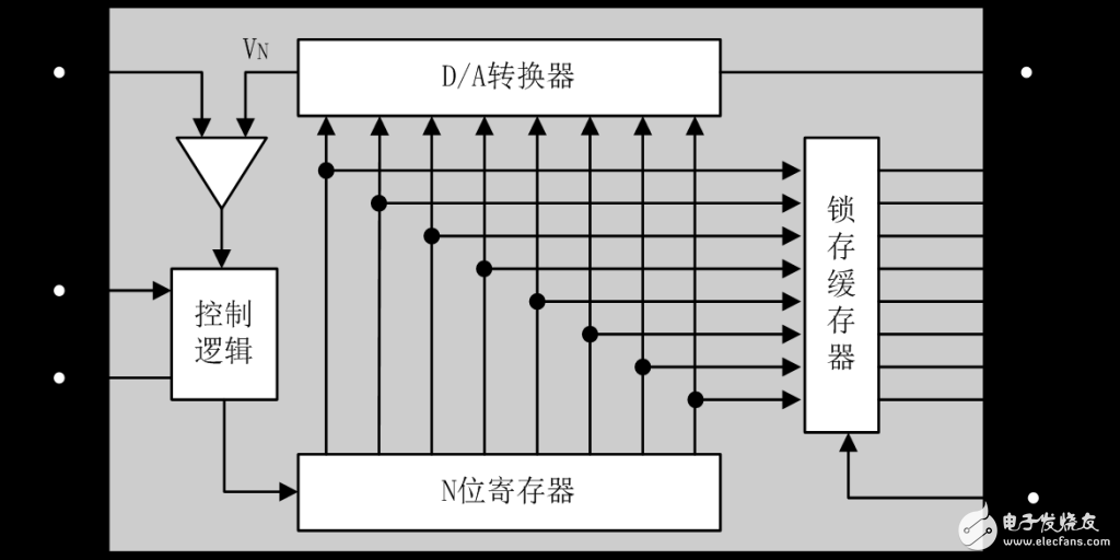
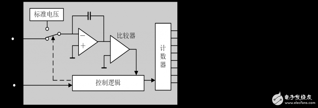
1, resolution
The resolution of the ADC is the amount of change in the input analog voltage required to vary the output digital amount by an adjacent digital. The number of bits in common binary is represented. For example, the resolution of a 12-bit ADC is 12 bits, or the resolution is 1/2^n of the full-scale FS. A 10V full scale 12-bit ADC can resolve input voltage changes with a minimum of 10V & TImes; 1 / 2^12 = 2.4mV.
2, quantization error
The ADC converts the analog quantity into a digital quantity and approximates the analog quantity by a digital quantity. This process is called quantization. The quantization error is the error caused by the quantization of the analog quantity by the finite number of bits of the ADC. In fact, to accurately represent the amount of analog, the number of bits in the ADC needs to be large or infinite. The maximum deviation between the step-like conversion characteristic curve of an ADC with a limited resolution and the ADC conversion characteristic curve (straight line) with infinite resolution is the quantization error.

3, offset error
The offset error is a value at which the output signal is not zero when the input signal is zero, so it is sometimes called a zero value error. Assuming that the ADC has no nonlinear error, the line connecting the midpoints of the conversion characteristic curve must be a straight line. The input voltage value corresponding to the intersection point of the straight line and the horizontal axis is the offset error.
4, full scale error
The full scale error is also known as the gain error. The full scale error of the ADC is the difference between the actual input voltage corresponding to the full scale output digital and the ideal input voltage.
5, linearity
Linearity, sometimes referred to as nonlinearity, is the maximum deviation of the converter's actual conversion characteristics from the ideal line.
6, absolute precision
In a converter, the maximum value of the difference between the actual analog input corresponding to any digital and the theoretical analog input is called absolute accuracy. For the ADC, measurements can be taken at the midpoint of each step, which includes all the errors.
7, conversion rate
The conversion rate of the ADC is the speed at which data conversion can be repeated, that is, the number of conversions per second. The time required to complete an A/D conversion (including settling time) is the reciprocal of the slew rate.
Four: AD080X demo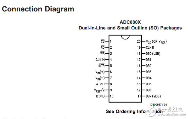
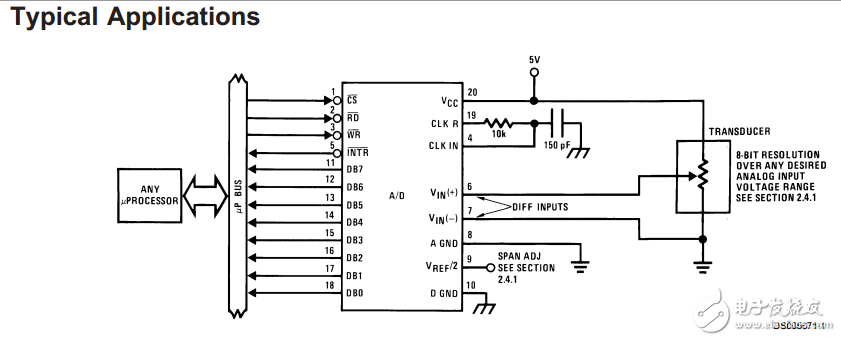
PIN5 If the CPU is notified by interrupt mode, it will be connected to the external interrupt. Otherwise, 5 can be left floating and the delay can be read directly.
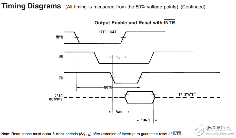
The startup sequence diagram is as follows:
Code demo:
[cpp] view plain copy print?
Void Launch()
{
CS = 0;
WR = 1; WR = 0; WR = 1;
/*WaiTIng for INTR goto 0*/
}

Read the timing diagram:
Code demo:
[cpp] view plain copy print?
Void ReadAD()
{
/* INTR had goto 0*/
CS = 0;
RD = 1; RD = 0; /*delay*/ RD = 1;
/* READ */
}
Instruction Manual
1. Features
Clock display, 10 sets of adjustable timed power control, randomized power control, manual switch and optional DST setup.
2. First time charging
This Timer contains a rechargeable battery. It is normal that the new/old model runs out of battery if it wasn`t being charged for a long period of time. In this case, the screen will not turn on.
To charge : simply plug the timer to a power outlet. The charging time should take at least 15 minutes.
If the screen doesn`t light up or displays garbled characters, simply reboot the system by pressing the [RESET" button.
3. Set clock
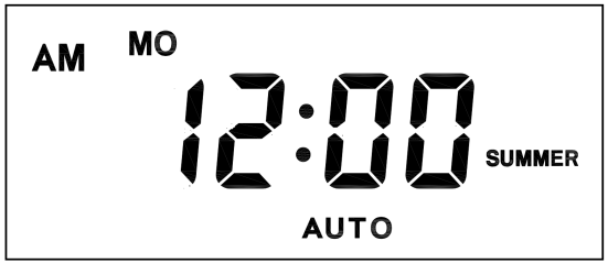
Hold [CLOCK" button and [WEEK" button to adjust week.
Hold [CLOCK" button and [HOUR" button to adjust hour.
Hold [CLOCK" button and [MINUTE" button to adjust minute.
Hold [CLOCK" button and [TIMER" button to select 12 hour/24 hour display.
Hold [CLOCK" button and [ON/AUTO/OFF" button to enable/disable DST (daylight-saving-time).
4. Set timer
Press [TIMER" button, select and set timer. Setting rotation : 1on, 1off, 2on, 2off, ...... , 10on, 10off.
Press [HOUR" button to set hour for timer.
Press [MIN" button to set minute for timer.
Press [WEEK" button to set weekday for timer. Multiple weekdays can be selected. ex: if selected [MO", the timer will only apply on every Monday; if selected [ MO, WE, FR", the timer will apply on every Monday, Wednesday and Friday.
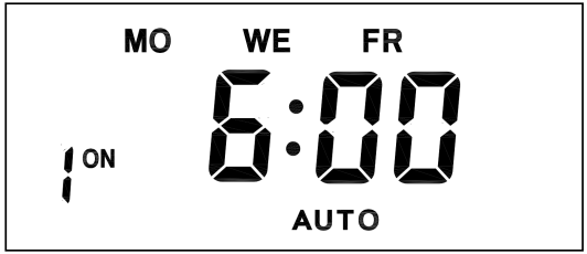
Press [RES/RCL" button to cancel the selected on or off timer. The screen will show "-- -- : -- --" , the timer is canceled.
Press [RES/RCL" button again to reactivate the timer.

When timers are set, press [CLOCK" to quit timer setting and return to clock.
5. Random function

Press [RANDOM" button to activate random function, press again to cancel function.
System only runs random function when [AUTO" is on.
Random function will automatically start the timer from 2 to 32 minutes after the setting.
ex : if timer 1on was set to 19:30 with the random function on, the timer will activate randomly between 19:33 to 20:03.
if timer 1off was set to 23:00 with the random function on, the timer will activate randomly between 23:02 to 23:32.
To avoid overlapping, make sure to leave a minimum of 31 minutes gap between different sets of timer.
6. Manual control
Displayed features:
ON : socket turns on.
OFF : socket turns off.
AUTO : socket turns on/off automatically via timer.
Manual ON setting
Press [ON/AUTO/OFF" button to switch from [AUTO" to [ON".
This mode allows socket of the device to power up. Power indicator will light up.
Manual OFF setting
Press [ON/AUTO/OFF" button to switch from [AUTO" to [OFF".
This mode turns socket of the device off. Power indicators will turn off.
7. Electrical parameters
Operating voltage : 230VAC
Battery : NiMh 1.2V
Power consumption : < 0.9W
Response time : 1 minute
Power output : 230VAC/16A/3680W
Q&A
Q: Why won`t my timer turn on?
A: It`s out of battery, you can charge the timer by plugging onto any power outlet. Charge the device for at least 15 minutes. Then press [RESET " button to reset the device.
Q: Can I set seconds of the timer?
A: No, the smallest time unit is minute.
Q: Does my timer keeps old settings without being plugged onto a power outlet?
A: Yes, the timer has an internal battery, it allows the timer to save settings without a power outlet.
Q: Is the battery rechargeable?
A: Yes, the battery is rechargeable. We recommend to charge it for 4 hours so the battery is fully charged.
Q: Does the timer needs internet connection?
A: The timer does not need internet.
Q: Does the screen have back light function?
A: It doesn`t support back light.
digital timer, digital timer socket, electronic timer socket, timer socket
NINGBO COWELL ELECTRONICS & TECHNOLOGY CO., LTD , https://www.cowellsocket.com