Introduction: In general, digital TV can be broken down into less than 10 major modules: display (and drive), core media engine, audio codec and processing, video codec and processing, tuner, interface module and power supply. The absolute performance requirements for each module are defined by the level of performance of the comfort experience of your favorite seat.
Whether driven by Moore's Law or consumer demand, the level of performance required in today's television may seem inconsistent.
Compared to standard definition television format (SDTV), digital TV with 1080 pixels of high definition (HD) format drives up to six times more data, managing digital TV, IPTV, video conferencing, and processing Dolby AC-3, MPEG and other audio formats, these features have become a must for digital TV (DTV).
From the highest requirements for audio, video and input signal formats, there are several options to choose from: front projection, rear projection, DLP, LCD, plasma and CRT. Whether you're watching a TV on a 1-inch display embedded in your watch, or watching TV on a whole wall with a projection system's display, the combination of size and performance is almost endless.
Digital TV Foundation
Even though every TV on the shelf today can be very different in terms of size, appearance, form factor and the basic description given to you by the salesperson, the basic building blocks of the TV are very different when you look inside. similar.
In general, digital television can be broken down into less than 10 major modules: display (and drive), core media engine, audio codec and processing, video codec and processing, tuner, interface module, and power supply. The absolute performance requirements for each module are defined by the level of performance of the comfort experience of your favorite seat.
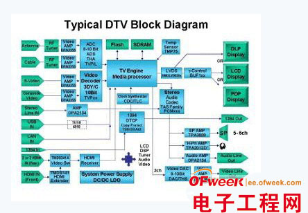
The figure below is a block diagram of a typical digital TV system.

Figure 1: Block diagram of a typical digital TV system
In Figure 1, we present the basic block diagram of HDTV, which we have considered at the functional block diagram level. The development of a television system behind the screen requires a number of tools that are available from a variety of businesses. However, in the process of integrating solutions from different component suppliers, it is necessary to speed up the design cycle to shorten the time to market and ensure compatibility. Whether using DLP technology, DSP-based digital media processors, other core processing solutions, or some other high-performance analog components, you need to design highly integrated, flexible, and easy-to-use numbers for the rapidly evolving digital TV market. TV set. For converged applications, designing high-performance audio and video CODEC, graphics acceleration, communication and support functions into the home entertainment experience system is critical.
Video design
Consumers often place very high demands on the video experience while watching TV. Because of this, resolution, brightness, contrast, and sharpness are important to the “realistic†experience that appears. For TVs, support for multiple ATSCTDV formats, NTSC and PAL decoding, composite and S-Video inputs, and 2D filtering are all critical. With the development of high-definition television, supporting full HD with 1080i resolution with 3D filtering will be the standard configuration. In the process of receiving the video signal chain as shown in Figure 1, it is important to select a video decoder, analog-to-digital converter (ADC) and video buffer with the ability to mix various functions so that you can The cost target adjusts performance.

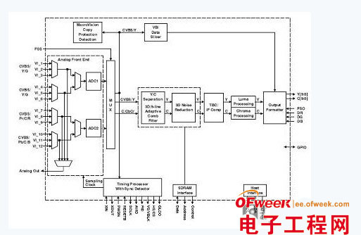
Figure 2: Data stream path of the video decoder
Figure 2 shows the data stream path of the video decoder, which is responsible for processing NTSC, PAL, SECAM, S-Video, SCART, YPbPr, RGB, 480p and other input formats. In digital TV, support for this level of flexibility is required, simply to allow a model to work in any format with actual settings. Typical performance characteristics of digital TV decoders include: sync, blanking, field, active video window, horizontal and vertical sync, clock, genlock (for downstream video encoding synchronization), main CPU interrupt, and programmable logic I/ O signal. This complements digital video output and data recovery for advanced vertical blanking (VBI). As an added feature, some video decoders support the VBI Data Processor (VDP) for data fragmentation, parsing, and error parsing on teletext broadcasts, subtitles (CC), and other VBI data. The built-in FIFO stores up to 11 lines of text TV broadcast data, and proper main interface synchronization and full screen text TV broadcast recovery are several common requirements in today's systems. However, some implementations require a decoder that can provide output formatted data at twice the speed of the sampled raw luminance data for the main CPU based VBI processing.
For ADCs in the signal chain, PC and HD video outputs require improved jitter reduction, higher image quality in video systems, and the ability to support ever-increasing bandwidth demands. In digital TV implementations, an 8/10-bit triple ADC typically provides a sampling rate of 165 Msps, providing rich video performance and is ideal for commercial projectors, televisions, and set-top boxes.
Finally, the video signal chain's output resolution is matched to the performance of the display and the resolution of the input signal to optimize the video design. In the low-resolution CRT TV era, a lower-performance front end may always be acceptable, but with today's high-resolution displays, any noise or irregular signals in the analog front end will be clearly displayed. Digital TV on the screen.
Audio design
In the past, consumers might have to connect their TVs to their home audio systems to enhance the audio experience, especially when watching movies. With the advancement of audio solutions, it is possible to separate TVs from home stereos in two different places, especially for digital TVs mounted on the wall, which has driven people to integrate advanced audio solutions directly into digital TV. Among them, to improve performance. However, whether driving surface speakers or traditional speakers, the audio signal chain is critical in maximizing the audio experience. In order to achieve further differentiation of audio quality, audio processing must be employed in digital television. Audio processing makes standard sound modes like movies, news, and music possible, as well as advanced audio features such as surround sound, subwoofer enhancements, and other well-known audio algorithms.
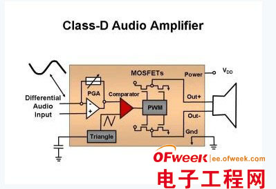
Tradeoffs in audio solutions are related to audio processing performance, audio output power, thermal dissipation, and overall power consumption. Traditional audio solutions consist of two to three speakers that are driven by Class AB audio power amplifiers. However, the operation of a class AB amplifier inherently generates a significant amount of heat relative to its overall audio output. These accumulated high temperatures prohibit the use of Class AB amplifiers in most thin form factor flat panel TVs because they require large heat sinks to dissipate heat. To solve this problem, the industry has adopted Class D amplifier technology (Figure 3). Currently, output field effect transistors (FETs) can be switched between a cut-off region and a saturation region to provide higher efficiency than a class AB amplifier. Existing audio solutions allow you to fully utilize the digital signal path. This not only maximizes audio efficiency, but they also provide efficient processing and signal-to-noise ratio (SNR) greater than 110 dB.

Figure 3: Basic topology of a Class D amplifier
Interface design
As people increasingly demand digital TV as a home communication portal, digital TVs and set-top boxes continue to add interfaces in addition to basic audio and video interfaces, including support for VGA, component video input (and often Output) and even HDMI; however, digital electronics may also support additional interfaces such as DVI, S-Video, IEEE 1394, USB, and LAN connections. In addition, with the rapid adoption of different low-power wireless interface technologies, each device from the remote control to the satellite speakers can easily communicate completely with the digital TV via radio.
Power supply design
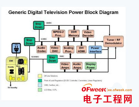
Most of the functional modules in the TV, including the AC/DC converters that create the main power source for the digital TV itself, require a special power solution, such as a backlight power supply for DLP lamps, LCD biasing, or displays, Core and I/O for the main processor, DDR memory, and power for the tuner and video/analog signal chain. Figure 4 shows the basic power distribution process for digital TV.

Figure 4: Typical Digital TV Power Requirements
In this era of energy efficiency, the government continues to develop new policies and tighten existing plans to cover the standby power consumption and efficiency of consumer electronics. At present, all plans to manage TV are voluntary, but the prospect of mandatory requirements is imminent. For example, in order to receive ENERGY STAR certification, digital TV cannot consume more than 3 watts of power in standby mode. Power factor correction (PFC) and green mode flyback converters can keep power consumption to a minimum in standby mode, and several new solutions have emerged in the market. At light loads, the power converter with burst mode operation provides a signal to turn off the bias supply to the PFC controller during standby, making it ideal for this application. Decisions about leveraging distributed power buses or local point-of-load power supplies are equally important compared to the performance of the entire system.
Summary of this article
Whether HDTV continues to follow the path we have seen before, or jump to a new development path – the new solution here requires you to project a 3D holographic image into the middle of the room in order to optimize the entire digital TV. Cost and performance, when making design decisions for any module in a digital TV, consider the requirements of the entire system. The lower-end power scheme leaves the noise in the signal path and is then compensated by the analog front end (AFE). Similarly, weaker AFEs attached to high-resolution displays do not fully exploit the advantages of the chosen display technology. In order to maximize the experience of sitting in front of a digital TV, the interoperability of each module in the system is absolutely critical.
We are 3535 Green SMD LED manufacturer from China.
All of our product are meet with Reach, CE, RoSH, SGS, EN62471 standards and have 5 years warranty.
We supply kinds of 3535 SMD LED with different wavelength from 365nm to 1550nm, which include the visible LED and the invisible LED.
In this catalog, we mainly introduce the 3535 Green SMD LED.
In this catalog, we mainly introduce the 3535 Green Smd LED of visible light. 3535 SMD LED, size is 3.0*3.6mm. For this Green SMD LED, we can package with single chip 3535 SMD LED or 2 chips 3535 SMD LED and the power can be 1W 3535 Green SMD LED, 2W 3535 Green SMD LED, 3W 3535 Green SMD LED and so on.
There have two kinds of the voltage on this green SMD LED: 1.8-2.5V and the 2.8-3.5V. The voltage of yellow-green SMD LED( 560nm LED -575nm LED) is 1.8-2.5V, they are not the normal product, but they do can't be ignored. Most of the Green SMD LED's voltage are 2.8-3.5V, like 3535 lime SMD LED, 3535 green SMD LED.
3535 Green SMD LED is deeply loved by their users because of the small size, the high bightnes and 3535 Green SMD LED have the cooling copper at the bottom, which can make the product to get out of the heat in time.
It is often used in LED lighting, LED Lamps , LED backlight, LED panel lights, LED furniture, landscape LED, LED Lighting, LED Lighting, led Backlight, LED Panel Light, LED Furniture, LED Photo Light, LED Aperture, LED Toys, grow light LED, fill light LED, LED aperture and other lighting products.
In addition, this 3535 Red SMD LED have the angle like the through-hole LED so it belongs to the spotlight SMD LED. It have a len on the top of the SMD LED, which can make this 3535 SMD LED with angle like 30 degrees, 60 degrees.
3535 Green SMD LED
Shenzhen Best LED Opto-electronic Co.,Ltd , https://www.bestsmd.com